Driver's Handbook on Cargo Securement - Chapter 1: Fundamentals of Cargo Securement


 Driver's Handbook on Cargo Securement - Chapter 2: General Cargo Securement Requirements


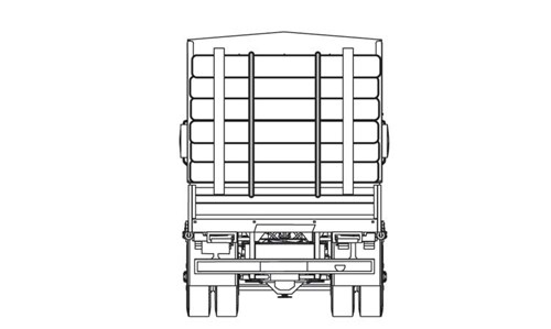
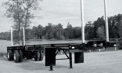
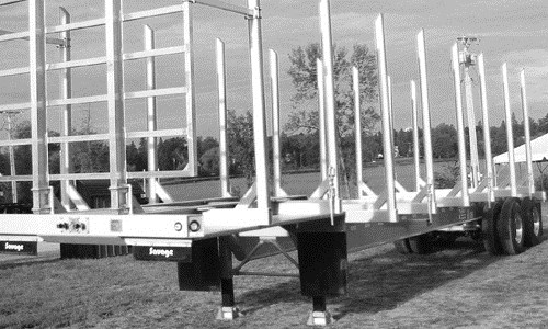
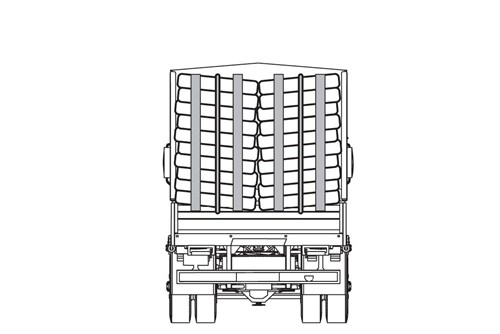
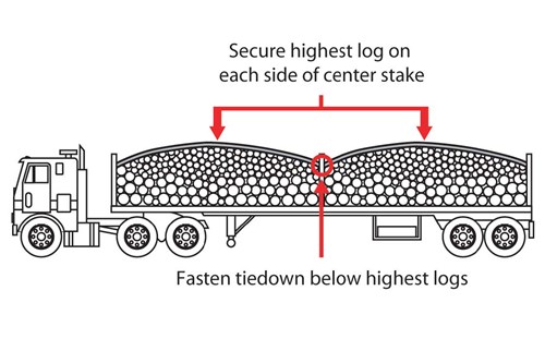
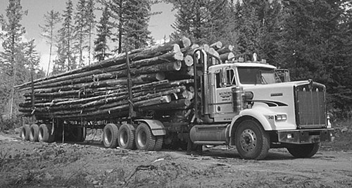
 Driver's Handbook on Cargo Securement - Chapter 3: Logs

What Does This Section Cover? (Section 3.2.1)
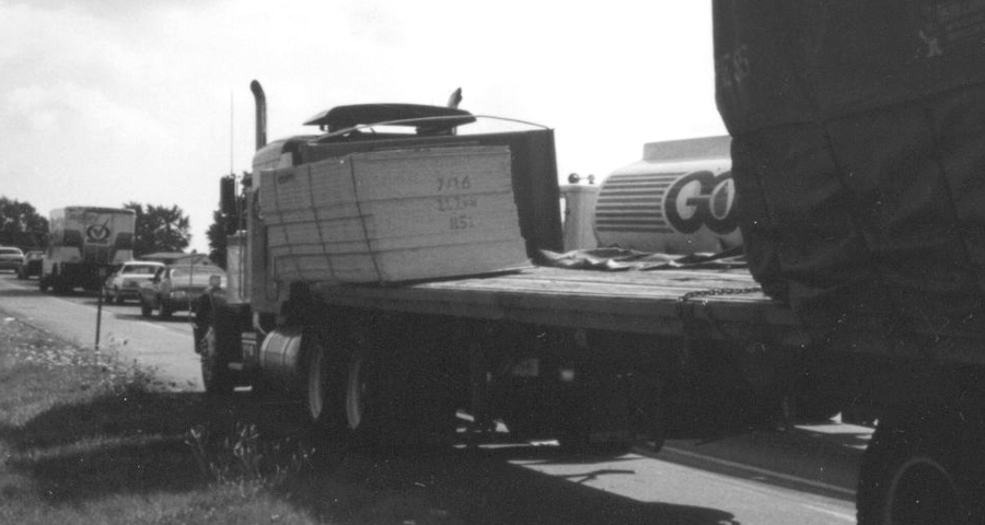
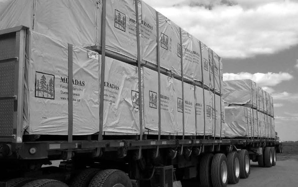
The requirements for dressed lumber and similar building materials section apply to certain products when they are transported as bundles on flatbed and open vehicles.
These products are:
- Dressed lumber.
- Packaged lumber.
- Engineered building products (e.g. plywood, drywall, other materials of similar shape).
Note: Lumber or building products that are not bundled or pack aged should be treated as loose items and transported in accordance with the general cargo securement requirements in Section 2.
Note: Bundles carried in a closed vehicle should be immobilized or contained in accordance with the general cargo securement requirements in Section 2.
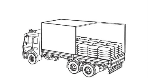
Positioning and Securing Bundles (Section 3.2.2)
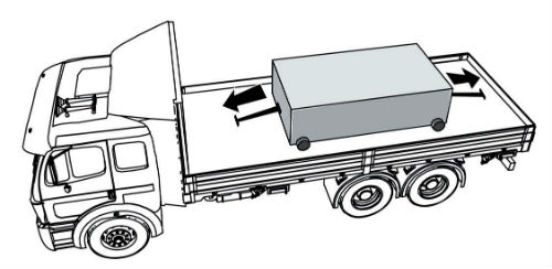
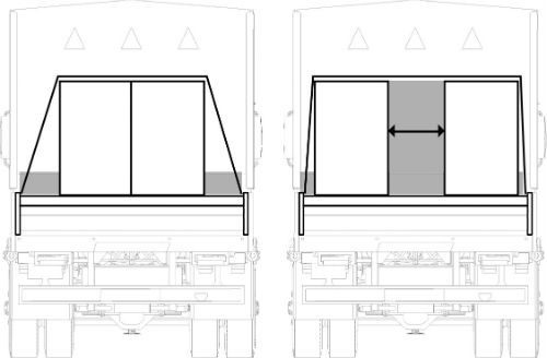
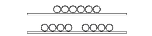
Requirements for bundles placed side by side on a platform vehicle
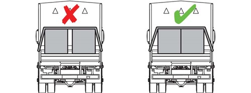
Choose one of two options for positioning bundles:
- Option #1:
- Place bundles in direct contact with each other.
- Option #2:
- Provide a means (such as dunnage or blocking) to prevent the bundles from shifting towards each other.
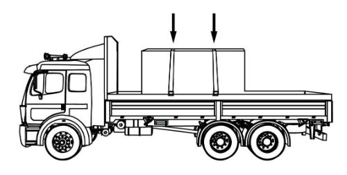
Requirements for bundles in one tier
- Secure bundles in accordance with general cargo securement requirements (Section 2).
- Web tiedowns are often used to secure building materials.
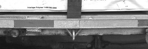
Requirements for Securement System:
- In proper working order with no damaged or weakened components that affect their performance or reduce their working load limit.
- No knots.
- Attached and secured in a manner that prevents them from coming loose during transit.
- Able to be tightened by a driver of an in-transit vehicle.
- Located inboard of rub rails whenever practicable.
- Edge protection must be used when a tiedown would be subject to abrasion or cutting.
Requirements for securing bundles in two or more tiers
There are four options for securing bundles of dressed lumber that are transported in two or more tiers. Choose one of the four.
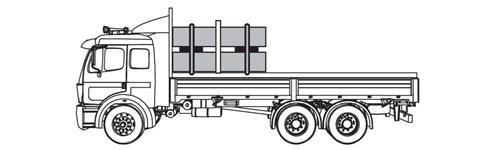
- Option #1:
- To block side-to-side movement, block the bundles with stakes on the sides of the vehicle. Secure the bundles by tiedowns laid out over the top tier, as outlined in Section 2.
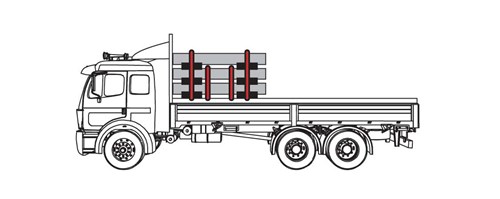
- Option #2:
- To block side-to-side movement, use blocking or high friction devices between the tiers. Secure the bundles by tiedowns laid out over the top tier, as outlined in Section 2.

High Friction Devices
- Friction mat
- Piece of wood with friction surface
- Cleated mat
- Other specialized equipment

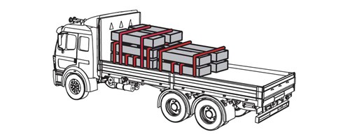
- Option #3:
- Place bundles directly on top of other bundles or on spacers.
- Secure the stack of bundles with tiedowns:
- Tiedowns over the second tier of bundles or at 1.85 m (6 ft) above the trailer deck (whichever is greater).
- Tiedowns for other multiple tiers not over 1.85 m (6 ft) above the trailer.
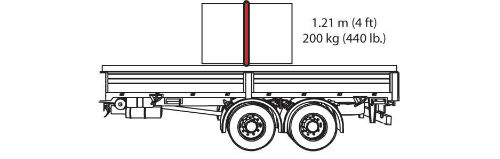
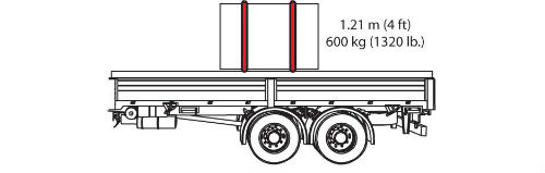
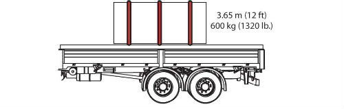
- Tiedowns over the top tier of bundles with a minimum of 2 tiedowns over each top bundle longer than 1.52 m (5 ft).
Spacer Requirements
- The length of spacers must provide support to all pieces in the bottom row of the bundle.
- The width of each spacer must be equal or greater than the height.
- Spacers must provide good interlayer friction.
- If spacers are comprised of layers of material, the layers must be unitized or fastened together to ensure that the spacer performs as a single piece of material.
- Option #4:
- Secure the bundles by tiedowns over each tier of bundles in accordance with the general cargo securement requirements (Section 2).
- Use at least 2 tiedowns over each bundle on the top tier that is longer than 1.52 m (5 ft).
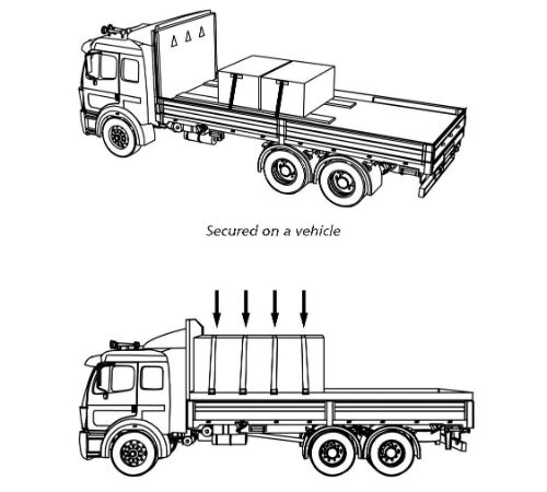
Suggestion to Increase Safety
Choose one of two options for stopping forward motion:
- Option #1
- Place bundles against bulkhead/front end structure.
- Option #2
- When different tiers need to be secured, use a combination of blocking equipment and tiedowns.

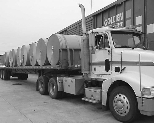
 Driver's Handbook on Cargo Securement - Chapter 5: Metal Coils

What Does This Section Cover?
This section applies to coils of rolled sheet metal. Coiled wire is secured using the general cargo securement requirements (section 2).
Size of coil (Section 3.3.1)
All metal coil shipments that, individually or together, weigh 2,268 kg (5,000 lb.) or more must be secured according to the specific requirements in this section.
Exception: Metal coils that weigh less than 2,268 kg (5,000 lb.) may be secured according to general securement requirements (Section 2).
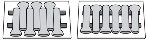
Orientation of coil
Eyes vertical
Eyes crosswise
Eyes lengthwise
Type of Vehicle
The specific requirements are for metal coils transported:
- On flatbed vehicles.
- In sided vehicles with or without anchor points.
- In intermodal containers with or without anchor points.
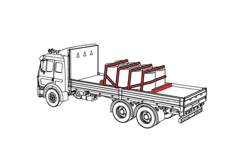
Securing Coils Transported With Eyes Vertical on a Vehicle with Anchor Points (Section 3.3.2)
If the coil is mounted on a pallet:
- Coil must be fastened to pallet so it cannot move on the pallet.
- Pallet must be strong enough to not collapse under Performance Criteria forces (Section 1).
- Use a friction mat between pallet and deck.
Requirements for securing a single coil (Section 3.3.2.1)
To prevent the coil from tipping forward, rearward, and sideways, arrange tiedowns to include the following:
- Attach at least one tiedown diagonally across eye of coil from left side of vehicle to right side of vehicle.
- Attach at least one tiedown diagonally across eye of coil from right side of vehicle to left side of vehicle.
- Attach at least one tiedown over eye of coil from side-to-side.
- To prevent forward movement, use one of these:
- Blocking.
- Bracing.
- Friction mats.
- A tiedown passed around the front of coil.
- Attach at least one tiedown against front of row of coils to restrain against forward motion.
- If possible, angle between tiedown and deck should be less than 45, when viewed from the side of the vehicle.
- Attach at least one tiedown against rear of row of coils to restrain against rearward motion.
- If possible, angle between tiedown and deck should be less than 45, when viewed from the side of the vehicle.
- Attach at least one tiedown over top of each coil or side-by-side row of coils to restrain against vertical motion.
- Tiedowns going over top of coil(s) must be as close as possible to eye of coil.
- Arrange tiedowns, blocking, or bracing to prevent shifting or tipping in all directions.
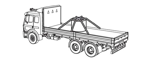
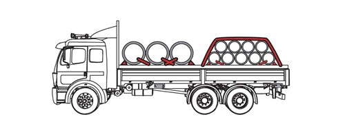
Securing Coils Transported With Eyes Crosswise on a Vehicle with Anchor Points (Section 3.3.3)
There are three requirements for coils transported with eyes crosswise:
Prevent the coil from rolling
- Attach one tiedown forward.
- Attach one tiedown rearward.
Requirements for securing a single coil (Section 3.3.3.1)
Prevent the coil from rolling
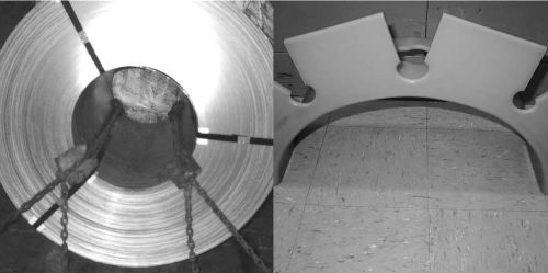
- Prevent the coil from rolling by supporting it:
- Timbers, chocks, or wedges held in place by coil bunks or similar devices to prevent them from coming loose.
- A cradle (for example, two hardwood timbers and two coil bunks) that is restrained from sliding by:
- Friction mats under the cradle.
- Nailed wood blocking or cleats.
- Placing a tiedown around the front of the cradle.
- The support must:
- Support the coil just above the deck.
- Not become unintentionally unfastened or loose in transit.
Note: The use of nailed blocking or cleats as the sole means to secure timbers, chocks or wedges, or a nailed wood cradle, is prohibited.
One tiedown forward
- Attach at least one tiedown through the eye of the coil to restrain against forward motion.
- If possible, the angle between the tiedown and the deck should be less than 45.
One tiedown rearward
- Attach at least one tiedown through the eye of the coil to restrain against rearward motion.
- If possible, the angle between the tiedown and the deck should be less than 45.
Note: Attaching tiedowns diagonally through the eye of a coil to form an X-pattern when viewed from above the vehicle is prohibited. (Section 3.3.3.2)

Note: If a tiedown is used around the front of the cradle, it does not count towards the aggregate WLL for tiedowns through the eye of the coil.
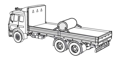
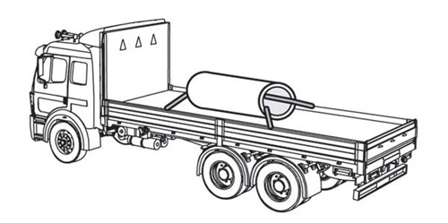
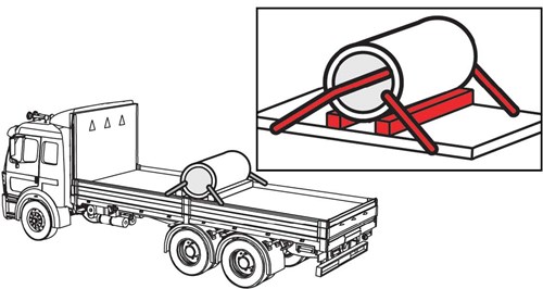
Securing Coils Transported With Eyes Lengthwise on a Vehicle with Anchor Points (Section 3.3.4)
Requirements for securing an individual coil
There are three options for safely securing individual coils that are loaded with their eyes lengthwise. Blocking and supporting the coils is the same. The difference is in the tiedown arrangement.
Eyes Lengthwise
Prevent the coil from rolling
- Prevent the coil from rolling by supporting it:
- Timbers, chocks, or wedges held in place by coil bunks or similar devices to prevent them from coming loose.
- A cradle (for example, two hardwood timbers and two coil bunks) that is restrained from sliding by:
- Placing friction mats under the cradle
- Using nailed wood blocking or cleats against the front timber
- Placing a tiedown around the front of the cradle.
- The support must:
- Support the coil off the deck.
- Not become unintentionally unfastened or loose in transit.
Note: The use of nailed blocking or cleats as the sole means to secure timbers, chocks or wedges, or a nailed wood cradle, isprohibited.
Tiedowns, Single Coil Option #1 (Section 3.3.4.1)
- Attach at least one tiedown diagonally from the left side of the vehicle, through the eye, to the right side of the vehicle.
- If possible, the angle between the tiedown and the deck should be less than 45, when viewed from the side of the vehicle.
- Attach at least one tiedown diagonally from the right side of the vehicle, through the eye, to the left side of the vehicle.
- If possible, the angle between the tiedown and the deck should be less than 45, when viewed from the side of the vehicle.
- Attach at least one tiedown side-to-side over the top of the coil.
- Use blocking or friction mats to prevent forward movement.

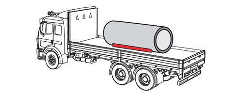
Option #1 Single Coil (Eye Lengthwise)
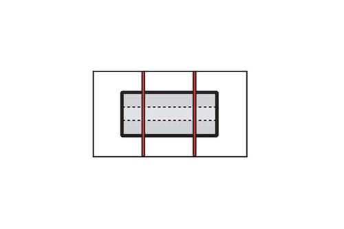
Tiedowns, Single Coil Option #2 (Section 3.3.4.2)
Option #2 is the same as Option #1, except the tiedowns that attach through the eye of the coil are straight instead of diagonal.
- Attach at least one tiedown straight from the left side of the vehicle, through the eye, and back to the left side of the vehicle.
- If possible, the angle between the tiedown and the deck should be less than 45, when viewed from the side of the vehicle.
- Attach at least one tiedown straight from the right side of the vehicle, through the eye, and back to the right side of the vehicle.
- If possible, the angle between the tiedown and the deck should be less than 45, when viewed from the side of the vehicle.
- Attach at least one tiedown side-to-side over the top of the coil.
- Use blocking or friction mats to prevent forward movement.
Option #2 Single Coil (Eye Lengthwise)
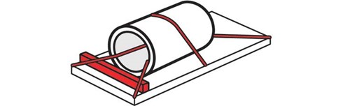
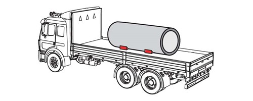
Tiedowns, Single Coil Option #3 (Section 3.3.4.3)
Option #3 is the same as Options #1 and #2, except that the two tiedowns that attach through the eye of the coil are replaced with two tiedowns that pass over the front and the rear of the coil.
- Attach at least one tiedown over the top of the coil near the front of the coil.
- Attach at least one tiedown over the top of the coil near the rear of the coil.
- Use blocking or friction mats to prevent forward movement.
Option #3 Single Coil (Eye Lengthwise)
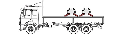
Requirements for securing rows of coils (Section 3.3.4.4)
A row of coils is three or more coils loaded in the same way and in a line.

Row of Coils
Prevent the coil from rolling
- Prevent the coil from rolling by supporting it:
- Timbers, chocks, or wedges held in place by coil bunks or similar devices to prevent them from coming loose.
- A cradle (for example, two hardwood timbers and two coil bunks) that is restrained from sliding by:
- Placing friction mats under the cradle
- Using nailed wood blocking or cleats against the front timber
- Placing a tiedown around the front of the cradle.
- The support must:
- Support the coil just above the deck.
- Not become unintentionally unfastened or loose in transit.
Note: The use of nailed blocking or cleats as the sole means to secure timbers, chocks or wedges, or a nailed wood cradle, isprohibited.
Tiedowns
- Attach at least one tiedown over the top of each coil or side-by-side row, located near the front of the coil.
- Attach at least one tiedown over the top of each coil or side-by-side row, located near the rear of the coil.
- Use blocking or friction mats to prevent forward movement.
Acceptable securement of a row of coils (Eyes Lengthwise)
Securing Coils Transported in a Sided Vehicle or Intermodal Container without Anchor Points (Section 3.3.5)
To prevent metal coils from moving horizontally and/or tipping:
- Follow general cargo securement requirements (Section 2).
- Secure the coils using:
- Blocking and bracing
- Friction mats
- A combination of these.
The securement system used must prevent movement in directions (see Section 1).
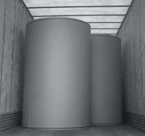
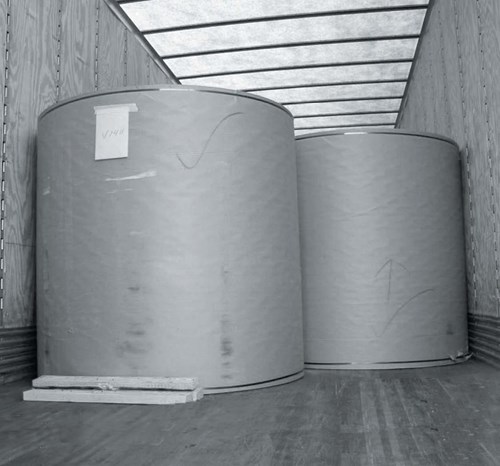
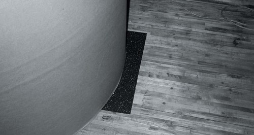
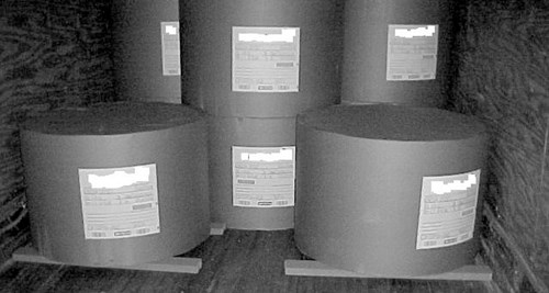
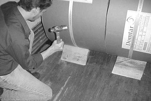
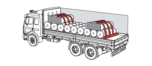
 Driver's Handbook on Cargo Securement - Chapter 6: Paper Rolls
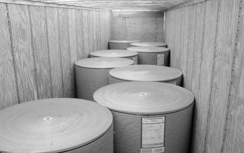


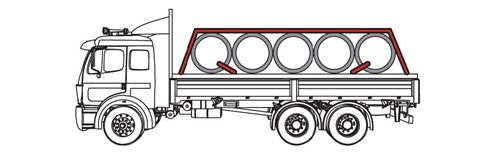
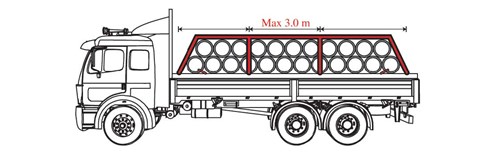
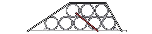
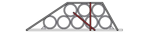
 Driver's Handbook on Cargo Securement - Chapter 7: Concrete Pipe Loaded Crosswise
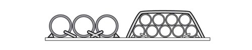


![[Diagram of bell pipes on the bottom row are layed in one direction and the pipes in the top row are alligned in the opposite direction. This top row only covers one end of the bottom row.]](http://www.fmcsa.dot.gov/sites/fmcsa.dot.gov/files/pictures/cargosecurement-16-04-rob-img-129_500px.jpg)
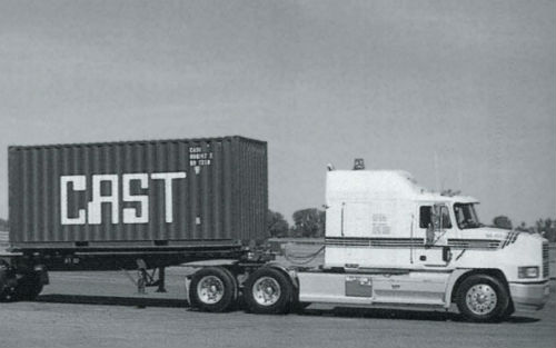
 Securement - Chapter 8: Intermodal Containers